
Last updated: September 2026
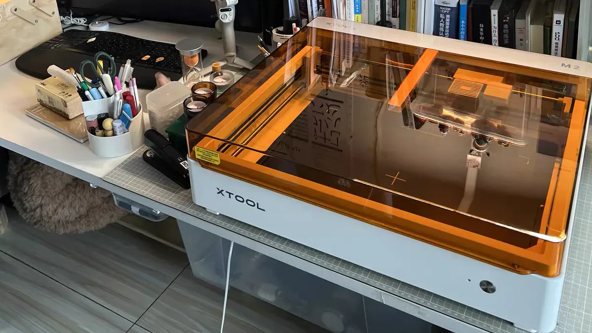
- How to Get the BEST Laser Engraving Settings begins with one rule: expect no universal number. The laser source and actual output affect the result. So do the material’s thickness and focus. The artwork matters too. Airflow and speed units matter too. Treat every chart as a starting range, then prove it on your machine with matching scrap.
- Verify the material and safety setup first. Then use the machine maker’s material guidance or a conservative range.
- Run a wide power by speed grid. Remove the failed zones, then test the useful range with smaller steps.
- Confirm the winner with real artwork. Save the machine and material, along with units and focus. Add the airflow and date.
Searching for a winning laser setting sounds like a hunt for one magic number. If one chart worked across every laser and material, your first engraving would already be perfect. Those charts feel reassuring when a costly blank is sitting on the bed. Yet a valid setting can fail after the laser, material batch, focus, artwork, or units change.
Reliable laser settings come from a small controlled experiment. You will test a broad range, find its useful zone, and narrow that zone. Then you will prove the result on the real design and save enough detail to repeat it.
Table of Contents
- How to Get the BEST Laser Engraving Settings in 2 Minutes
- What You Need for a Reliable Laser Settings Test
- Check Laser Material Safety Before Testing Any Settings
- Laser Speed and Power Need the Correct Units
- Run a Speed and Power Material Test in LightBurn
- Read the Laser Test Grid, Then Narrow the Useful Range
- Test Engraving and Cutting Apart From Bitmap Photos
- Tune Advanced Laser Controls After the First Grid
- Validate the Winning Laser Setting With Real Artwork
- Save Laser Settings With Enough Context to Reproduce Them
- Laser Engraving Settings Troubleshooting Table
- Frequently Asked Questions About Laser Engraving Settings
- Better Laser Settings Come From a Repeatable Test
How to Get the BEST Laser Engraving Settings in 2 Minutes
Find the best settings by testing one known material on your own machine. Use a wide two variable range first, then retest the promising range in smaller steps.
- Confirm the material is laser safe. Record its exact type and thickness.
- Set focus and exhaust. Lock the air assist and artwork. Confirm the speed units.
- In LightBurn, open
Laser Tools → Material Test. Choose Speed and Power. - Use the maker’s published baseline or a conservative high speed, low power range.
- Preview and Frame the grid. Run it while staying beside the machine.
- Reject faint and damaged cells. Retest the useful band, then engrave your real design.
“Best” needs a job description. You may want high contrast, fine detail, extra depth, a fast cycle, or a clean cut. Pick the lowest energy or fastest result that still meets that goal.
What You Need for a Reliable Laser Settings Test
A useful test kit is small. You need matching scrap, the machine’s focusing method, working exhaust, your normal air setup, a test pattern, and a way to label the result.
| Item | Why it matters | Keep fixed | Record afterward |
|---|---|---|---|
| Same batch scrap | Matches the final stock | Face and orientation | Material and supplier |
| Caliper or known thickness | Confirms the actual stock | Test thickness | Measured thickness |
| Focus gauge or autofocus | Controls spot placement | Focus method | Focus or offset |
| Exhaust and air assist | Changes smoke and heat | Normal operating state | Air setting |
| LightBurn Material Test | Makes a labeled grid | Test pattern | Winning range |
| Marker or digital log | Preserves context | Naming format | Date and photo |
Keep the machine manual, manufacturer material guidance, and safety data sheet nearby. They are working tools. If LightBurn itself is still unfamiliar, start with our LightBurn beginner tutorial.
Check Laser Material Safety Before Testing Any Settings
Do not test an unknown material. Confirm the manufacturer’s description and safety data sheet first. Keep PVC, vinyl, chlorine containing stock, and unidentified plastics out of the machine.
xTool’s material safety guidance warns against PVC, vinyl, materials containing chlorine, and unknown materials. Glowforge also advises checking the manufacturer and SDS for custom stock. A test grid cannot make unsafe stock safe.
Prepare the machine before you chase appearance. Use the enclosure or guards required by the manual, start the specified exhaust, clear the bed, and use protection required by the machine manual and local rules. Keep your fire response plan ready and stay with the laser for the entire test.
Laser source changes the calibration question. Use this compact map before choosing variables:
| Laser source | Common starting job | First controls to test | Boundary |
|---|---|---|---|
| Diode | Wood, slate, coated stock | Speed, power, focus | Coating and wavelength matter |
| CO2 | Wood, acrylic, some glass work | Speed, power, focus, air | Material approval still matters |
| Fiber or MOPA galvo | Metal marking and depth work | Speed, power, frequency | Use source specific guidance |
| UV galvo | Sensitive surface marking | Speed, power, frequency, Q-Pulse | Only supported controls apply |
Low speed and high power cells place the most heat into the material. LightBurn’s First Material Test guide specifically warns against leaving these tests unattended. Its test order starts in the safer high speed, low power corner.
Laser source also changes material compatibility. Our diode vs CO2 vs IR laser guide explains the practical differences before you select a test range.
Laser Speed and Power Need the Correct Units
Speed controls exposure time. Power controls the selected output level. The speed unit determines what the number actually means.
Think of the beam as a marker moving across paper. A slower hand leaves more time on each spot. On the same machine and material, slower movement usually creates a darker or deeper result.
More power usually pushes in the same direction within a tested window. Heat response can stop being linear.
Your software may display mm/s or mm/min. The same number represents speeds that differ by a factor of 60. Units can ruin this test. A settings post that omits its unit has omitted the setting.
| Control | Plain meaning | Typical visible effect | Test it when | Device boundary |
|---|---|---|---|---|
| Speed | Travel rate | Slower often gets darker or deeper | First grid | Units must match |
| Power | Selected output | More can deepen or char | First grid | Percent is machine specific |
| Focus | Beam waist position | Changes sharpness and energy density | Before every grid | Follow the machine method |
| Passes | Repeat count | Adds depth and heat | After one pass | Useful for some cuts |
| Interval or DPI | Scan line spacing | Changes overlap and time | After base range | Mainly filled images |
| Frequency | Pulse rate | Changes pulse interaction | After base range | Common on galvo systems |
| Q-Pulse | Pulse width | Changes pulse behavior | Last | Supported MOPA fiber and UV galvo only |
A 10W diode setting cannot define a CO2 or galvo setting. Even two 10W modules can differ in spot size, optics, focus, controller behavior, and wear. Wattage gives you context. It does not finish the test.
Run a Speed and Power Material Test in LightBurn
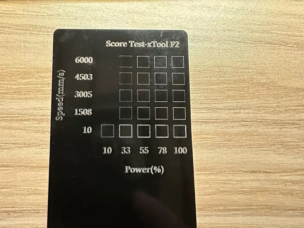
LightBurn’s Material Test creates a labeled comparison grid. One variable changes across the columns, while another changes down the rows. You can compare dozens of controlled combinations on one piece of scrap.
1. Lock the Test Conditions
Record the machine, laser source, material, thickness, focus method, air setting, image mode, and speed unit. Use one consistent fill pattern across the cells. A changed focus or air setting turns your clean comparison into several different experiments.
2. Open the Material Test Generator
Choose Laser Tools → Material Test, then select Speed and Power. LightBurn’s Material Test documentation shows a default 10 by 10 grid and lets you change the count. Supported variables depend on the device.
Speed and power are common choices. Interval and passes are common too. Frequency and Q-Pulse appear on supported sources.
3. Choose a Broad, Conservative Range
Use official manufacturer guidance when it exists. Otherwise, begin in a high speed, low power region and widen gradually. Your first grid should reveal faint cells, useful cells, and excessive heat without treating any online number as a promise.
4. Preview and Frame While You Stay With the Machine
Preview the job and Frame the boundary. Confirm that every cell sits on scrap. Keep watching. Start in LightBurn’s safer order, especially as the test moves toward slower and stronger cells.
Read the Laser Test Grid, Then Narrow the Useful Range
The first grid finds boundaries. It is reconnaissance. The second grid finds a useful operating window. Reject cells that are faint, scorched, melted, blurry, incomplete, or needlessly slow.
Inspect the sample in normal room light. Check the back and edge when you are testing a cut. A photo can fool you. It may hide texture, depth, melt damage, and small differences in contrast.
| What you see | Likely direction | Next single change | Check first |
|---|---|---|---|
| Faint mark | Too little exposure | Slow down or raise power | Focus and units |
| Swollen detail | Too much exposure | Speed up or lower power | Artwork size |
| Charred wood | Excess heat or smoke | Reduce exposure | Air and exhaust |
| Melted edge | Excess heat | Speed up or lower power | Material identity |
| Scan gaps | Lines too far apart | Reduce interval | Focus and spot size |
| Muddy photo | Too much overlap or poor mode | Widen interval or test mode | Source image |
| Incomplete cut | Too little depth | Slow down or test another pass | Focus and back side |
Circle the acceptable band. Build a second grid around that band with smaller increments. If several cells look equal, choose a stable group and favor the faster or lower energy member that still meets your goal.
Build Dad Build’s material test demonstration also checks the front and back of cut samples. Make or Break Shop’s test file comparison compares physical samples under different light. Both practices protect you from choosing a square that only looks good on screen.
For the wider preparation sequence around this test, use our laser engraving preflight and quality checks.
Test Engraving and Cutting Apart From Bitmap Photos
One grid cannot validate every job. Filled engraving and vector cutting stress different controls. Small text and logos reveal other weaknesses. Bitmap photos add tonal demands.
For a filled mark, judge contrast plus edge quality and scan line overlap. A cut test needs a closed contour. Inspect release, kerf, edge char, and the back face. When one file contains both operations, engrave first and cut the closed outer contour last.
Text and logo coupons should include thin strokes and small type. Photo tests need highlights and shadows, plus fine detail and a grayscale range. That comparison separates cut files and logos from bitmap modes and line density because each asks a different question.
Marking anodized aluminum also differs from deep engraving bare aluminum. Our guide to engraving anodized aluminum with a diode laser explains that boundary.
Tune Advanced Laser Controls After the First Grid
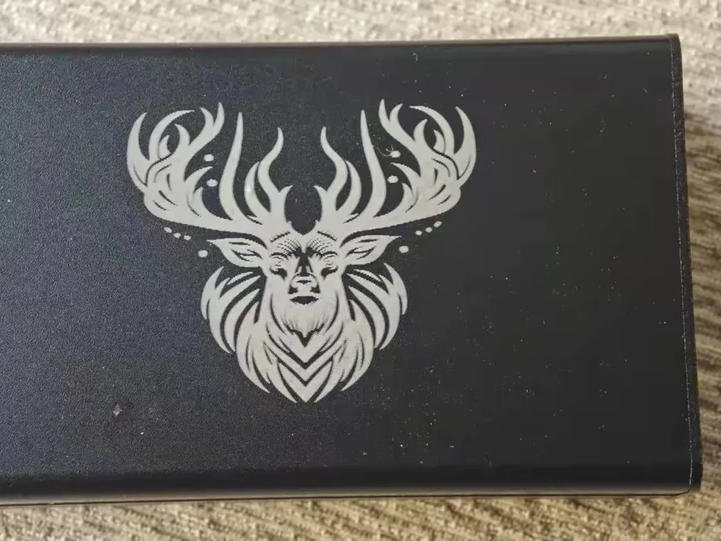
Stabilize speed and power first. Then test one advanced control at a time, using the useful range you already found.
A smaller line interval places scan lines closer together. It can darken a fill and extend the job, yet extra overlap cannot create detail beyond the focused spot. More lines cost time. One documented S1 wood test favored 200 lines per centimeter over 300, which warns against assuming that more resolution always wins.
An image settings demonstration uses gradients and several text sizes to expose weak contrast, lost detail, and overburn before production.
Test extra passes for depth or cutting after you understand one pass. Galvo and fiber users may also test frequency. LightBurn exposes Q-Pulse width only for supported MOPA fiber and UV galvo sources, according to its galvo settings documentation. Frequency and pulse behavior vary by source, so use the documented device window.
Only after Speed and Power are stable should you evaluate image mode alongside scan spacing. This keeps the photo test focused on one new variable.
To reduce engraving time, test a wider interval or more speed. Lower unneeded resolution or simplify the paths in separate trials. Check the required detail after each change.
Validate the Winning Laser Setting With Real Artwork
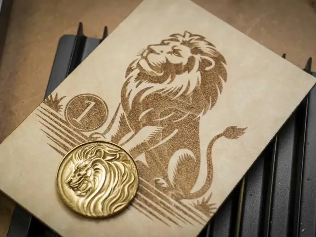
A grid winner becomes a production setting after the real design passes on matching scrap. Use a coupon with solid fill and fine lines. Add small text and curves, plus a grayscale ramp when photos matter.
Steve Makes Everything’s documented 60W MOPA workflow needed three rounds of narrowing. The chosen range still went through a real artwork test before it entered the material library. That extra run caught details a matrix of plain squares could miss.
Inspect contrast and texture. Then check the edges and depth. Record the total time. For valuable blanks or a batch, approve one finished piece before committing the rest.
Save Laser Settings With Enough Context to Reproduce Them
Save the successful preset in LightBurn’s Material Library and keep the labeled test card. A preset called “Wood good” will become a small mystery by next month.
Record the machine and laser source. Add material details, including the supplier and batch. Save its finish and thickness. Then record the task, focus, speed with its unit, power, passes, interval, air, date, result photo, and maintenance state.
Name every preset clearly. 3mm birch ply / fill logo / 10W diode / Sep 2026 is searchable. Steve Makes Everything’s MOPA workflow saves the tested material and thickness with the machine and task in LightBurn, then exports a backup.
Retest after changing the supplier or batch, thickness, lens, laser module, focus method, or airflow. Also retest after maintenance changes output or when quality drifts without an obvious cause.
Laser Engraving Settings Troubleshooting Table
Check the material and setup before moving several sliders. One changed variable gives you a result you can explain.
| Symptom | First check | Next single change | Stop condition |
|---|---|---|---|
| Faint engraving | Units, focus, clean optics | Slow down slightly | Smoke or surface damage |
| Excessive char | Material and exhaust | Increase speed | Flame or unsafe fumes |
| Muddy image | Source image and focus | Widen line interval | Lost required detail |
| Uneven result | Flatness and grain | Rotate or replace scrap | Unknown material behavior |
| Visible scan lines | Focus and spot size | Reduce interval | Extra overlap adds blur |
| Incomplete cut | Focus and back face | Reduce speed | Excessive char or flame |
| Old preset now fails | Batch plus lens and airflow | Run a fresh small grid | Cause remains unexplained |
For a faint mark, clean optics and confirm focus before adding heat. If a cut already passes through but its edge is black, Big Blue Laser Designs’ speed and power walkthrough supports increasing speed or reducing power in small steps. Your target is the cleanest setting that still completes the job.
Frequently Asked Questions About Laser Engraving Settings
What are the recommended speed and power settings for laser engraving?
The reliable way to learn how to get the BEST laser engraving settings is to test your own setup. Begin with the laser maker’s current material table, confirm the speed unit, and run a grid on matching scrap.
What are the recommended settings for a 10 watt laser engraver?
Ten watts only describes part of the setup. You still need the laser type and material. Add thickness and focus, plus the operation and units, before choosing a range.
What are the best settings for image engraving in LightBurn?
Find a safe speed and power region first. Then vary the controller’s image mode and scan spacing with a grayscale image containing bright and dark regions, along with fine detail.
How to adjust power and speed in LightBurn?
Edit Speed and Max Power in the relevant Cuts/Layers setting for a real job. Use Laser Tools → Material Test when you want a labeled comparison across many combinations.
How to test material in LightBurn?
Open Material Test and choose two variables with conservative ranges. Preview, Frame, supervise the run, label the sample, and save the useful range.
What is the pattern used in a laser engraving test?
A basic test uses a labeled matrix of filled squares. Add separate coupons for vector cuts and small text. Use other coupons for logos and gradients. Bitmap photos need their own test.
How to speed up laser engraving time?
Try a higher speed or wider line interval. Test lower resolution and simpler paths separately, then confirm that the required appearance remains.
What are the recommended power settings for laser engraving glass?
Glass needs guidance for the specific laser source, glass product, and surface method. Test scrap under that guidance, then stop if you see cracking, chipping, or flaking.
What are the recommended material settings for a laser engraver?
Manufacturer libraries provide starting points. Your saved setting should identify the material batch, thickness, laser source, task, focus, speed unit, and other active controls.
What are some tips and tricks for successful laser engraving?
Use known material, correct focus, working exhaust, matching scrap, and a labeled test grid. Validate the real artwork and record every setting that affects the result. See our laser engraver guide by material and use when you are still choosing a machine.
What are the recommended image settings for laser engraving?
Use an image mode that your controller supports, then test its line interval on a grayscale coupon. The correct choice depends on the laser spot, material surface, and detail you need.
What are the best settings for engraving in LightBurn?
The best LightBurn setting is the cleanest cell from a controlled Material Test that matches your real artwork. Save the winning range with its speed unit and material details.
What are the best speed and power settings for LightBurn lasers?
Run the LightBurn grid on your own machine and material. Use source guidance as a starting window, then narrow it with the same focus and airflow.
What are the typical settings for a laser engraving machine?
Typical values are machine and material specific. A useful record names the source and stock. Add thickness, focus, speed unit, power, and interval. Record passes and date.
Better Laser Settings Come From a Repeatable Test
The best laser engraving setting is the cleanest repeatable result your machine produces on the real material for the real job. Verify the stock, lock the conditions, test broadly, narrow the useful range, and validate the design.
On your next job, circle the useful cells and rerun that range with smaller steps. Save the winner with its units and test card. You do not need a perfect first guess when your method makes the second attempt predictable.