
I earn a commission if you buy through links on this page, at no extra cost to you. As an Amazon Associate, I earn from qualifying purchases.
If your model is larger than the build plate, splitting can feel easy. Then you notice the seam. The alignment pins follow. Six pieces still need sensible print orientations.
Learning how to split a 3D model into parts is mostly a planning job. The Cut button takes seconds. A poor cut can leave you with pieces that fit the printer and refuse to fit each other.
This guide gives you the fast slicer method first. You will also learn where to place cuts and how to add connectors. Harder jobs get a proper modeling workflow.
Table of Contents
- First, Decide What “Split” Means for Your Model
- How to Split 3D Model Into Parts in a Slicer
- Where Should You Cut a 3D Model?
- Add Alignment Pins and Joints That Actually Fit
- How to Split a Model in PrusaSlicer
- How to Split a Model in Bambu Studio or OrcaSlicer
- Use a Modeling Tool or Online Splitter for Harder Cuts
- Test One Joint Before Printing Every Part
- Common Mistakes That Ruin Split Models
- Join and Finish the Printed Parts
- FAQ
First, Decide What “Split” Means for Your Model
Splitting can mean three different operations. You may separate disconnected shells or cut one mesh. You may also design new mating parts. Check the file first.
An STL may contain several disconnected shells while appearing as one object. “Split to objects” can separate those existing shells, but it cannot invent a cut through a truly solid mesh. A plane cut creates new surfaces through that mesh.
A 3MF can carry more than geometry. It may retain object relationships and colors. Paint data or slicer settings may also live inside it. Save the editable project first.
| What you need | Best starting point | Why it works | Main limit |
|---|---|---|---|
| Straight cut for printing | Slicer Cut tool | Fast and visual | Mostly planar cuts |
| Automatic oversized sections | Browser splitter | Reduces repetitive work | Output still needs inspection |
| Curved or face-level separation | Blender or mesh editor | Direct mesh control | Harder for beginners |
| Precise functional joints | Fusion 360 or CAD | Controlled bodies and dimensions | Imported meshes may need cleanup |
| Painted model by color | Color-aware 3MF workflow | Can preserve paint regions | Tool and file limits vary |
If you are still choosing software, our best slicer for 3D printing guide explains which ecosystem fits each printer.
How to Split 3D Model Into Parts in a Slicer
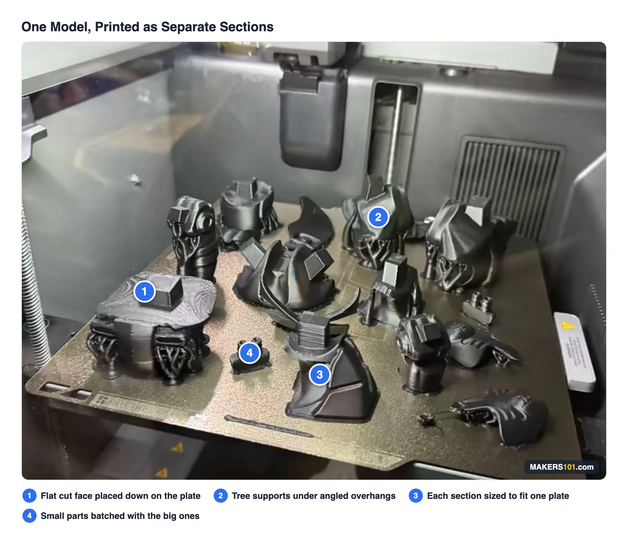
The quickest method takes four actions. Import the model and open Cut. Position the plane, keep both pieces, then orient the new faces. Add connectors before confirming.
1. Import the model and check its size
Select the object and read all three dimensions. Compare every axis with the usable build volume. Include clips and excluded edges.
Leave some margin. One large-part workflow used 250 mm sections on a printer with a 256 mm cubic build volume. The creator did not state that the 6 mm difference was intentional clearance, so treat these as case dimensions rather than a general rule.


2. Position the cutting plane
Move the plane through a region with enough material on both sides. Rotate it when another angle improves bed contact. It may also reduce supports or hide the seam.
Avoid creating tiny islands. They print poorly and disappear easily. Their presence usually means the plane needs adjustment.
3. Keep and orient the new pieces
Choose the option that keeps both sides. Some slicers let the result remain as two parts of one object or become two independent objects, so read that label carefully.
Placing the fresh cut face on the bed often removes support. It can also put the layer lines in a weaker direction, so preview the load path before accepting the convenient orientation.
4. Add connectors and save the project
Choose the connector by geometry. Plugs and dowels handle simple alignment. Snaps or dovetails need walls thick enough to support them.
Save the editable project or 3MF before exporting individual meshes. Connector sockets may be represented as negative volumes inside the project, and a careless STL export can lose that relationship.
Where Should You Cut a 3D Model?
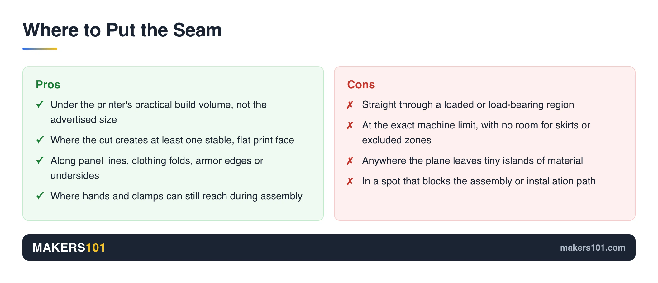
Place each seam where the pieces fit and print cleanly. Check the load and assembly path too. The shortest cut can be the worst cut.
Fit the usable build volume
Size every section below the printer’s practical limit. If you use an Ender machine, the physical plate and printable area are not always the same; our Ender 3 bed-size guide explains that difference.
For a very large project, model a smaller build-volume box. Intersect it with the design to create one printable section. Move it. Repeat.
Gaps and overlaps become easier to spot.
Improve orientation and reduce support
A useful cut creates at least one stable print face. It may also improve a delicate feature’s orientation. Its layers can then follow the load.
Do not trade every support for a weak joint. A decorative helmet and a loaded bracket need different seam strategies.
Hide the seam and preserve assembly access
Panel lines and clothing folds can disguise a joint. Armor edges and undersides work too. Your hands and clamps still need access during assembly.
Large assemblies also need a realistic installation path. A car-part case from the private research found that making the biggest possible subassembly complicated installation and contributed to cracking. Transport and repair matter too.
Add Alignment Pins and Joints That Actually Fit
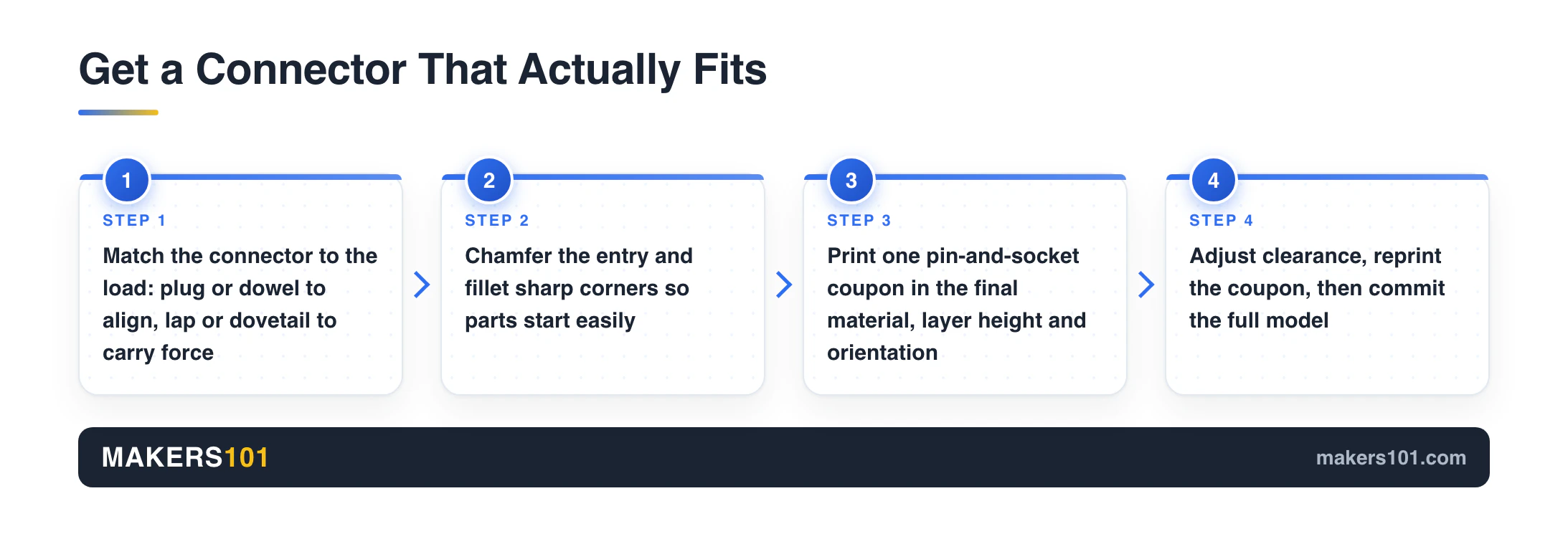
A printable connector needs clearance and a guided entry. It also needs enough socket wall and a workable assembly direction. Print one small test pair. CAD cannot predict the final fit.
Match the connector to the job
Use a plain butt joint for light decorative parts when glue area is sufficient. A dowel or plug aligns two faces, while a lap joint adds registration and bonding area.
Loaded parts deserve more thought. A flat glued seam concentrates risk at one plane. A wedge or dovetail can restrain movement mechanically and transfer load through the geometry.
Treat clearance as a test value
Material and color affect the finished dimensions. Nozzle choice adds variation. Layer height and infill do the same. Shrinkage and calibration complete the picture.
One large-part case used a 5 × 5 × 28 mm alignment pin. A separate compliant-feature example used a 0.3 mm gap beneath a flexible element. That 0.3 mm value was not a pin-to-socket clearance. Test the actual joint on your printer.
Make the connector easier to assemble
Add a chamfer to the entrance of a pin or socket. It guides the parts together and helps the joint clear a small elephant-foot lip.
Fillets around sharp connector corners reduce stress concentration and distortion. Slots or flexible grip fins can absorb small dimensional changes. Thin compliant walls can help too.
A 3D printer calibration cube can reveal broad dimensional error. Your final decision should still come from a connector coupon printed in the same orientation and material as the real part.
How to Split a Model in PrusaSlicer
Select the model and press C for PrusaSlicer’s Cut tool. Choose Planar or Dovetail mode. Position the cut, add connectors, then set each result’s bed orientation.
Make a planar cut
Move the cutting widget along any axis. You can enter an exact Z position and rotate the plane for an angled cut.
PrusaSlicer also lets you keep selected regions connected when the plane crosses several separate areas. This is useful when one cut intersects details you did not intend to separate.
Add alignment hardware
According to the official PrusaSlicer Cut Tool guide, Plug creates a male feature and matching socket. Dowel creates sockets on both sides plus a separate pin. Snap adds a snap-fit feature and its matching recess.
You can change the connector’s shape and size. Depth and rotation are adjustable too. Keep enough material around every socket.
Use Dovetail mode when it suits the geometry
Dovetail mode creates a trapezoidal pin-and-tail joint across the cut plane. It can restrain movement better than a plain face, but it still needs clearance and a valid assembly direction.
How to Split a Model in Bambu Studio or OrcaSlicer
Bambu Studio and OrcaSlicer use a similar visual workflow. Open the Cut gizmo after selecting your model. Place the plane and keep the required sections.
Add connectors when available. Save the project before export.
Bambu Studio
Import the model on the Prepare screen and select it. Open Cut from the toolbar or object menu, then move and rotate the plane through the model.
Choose which sides to keep and review the connector options shown in your installed release. Bambu Studio changes faster than many written tutorials, so trust the labels in your current dialog when an older screenshot disagrees.
OrcaSlicer
Press C with the model selected to open OrcaSlicer’s Cut gizmo. The current OrcaSlicer keyboard-shortcut documentation also lists U for Measure and Y for Assemble. Both help during preflight.
Inspect exported parts before closing the project. OrcaSlicer developers have explained that connector holes can exist as negative parts. A child-only mesh export may omit the socket operation. Keep the editable project.
Use a Modeling Tool or Online Splitter for Harder Cuts
Move beyond a slicer when the seam must follow a curve or create controlled CAD bodies. Modeling tools also handle loaded joints and repeated sections. They may preserve painted 3MF data through specialized workflows.
Fusion 360: precise bodies and functional joints
For native solids, create a construction plane or surface and use Split Body. Imported STL meshes may require mesh tools or conversion before every solid-modeling command becomes available.
Fusion 360 can divide one design into multiple bodies with Extrude and Combine. Use Cut where needed. Build interfaces while the parts still share a common origin. ChatGPT can now drive Fusion for simple bodies like these, but you still check every joint it builds. Here’s what the ChatGPT setup can and can’t model.
For repeated large sections, make a box slightly smaller than your printer’s volume and use Boolean Intersection. Moving that box through the complete design creates controlled chunks while preserving the overall form.
Blender: curved and face-level separation
Use Separate by Loose Parts when the file already contains disconnected shells. A continuous mesh needs a face selection or defined cut. Close the new boundaries before separating the geometry.
Dense or non-manifold meshes make this harder. Run a mesh check after the cut and confirm that every new boundary is watertight before slicing.
Online splitters: fast automation with caveats
Browser tools can automatically fit oversized models to a chosen bed size. Some also generate alignment holes and batch-download the results.
Review where the file is processed and check its size limit. Confirm that the tool closes every cut surface. The STL Splitter page warns that complex intersections can produce non-manifold edges or incomplete caps.
Color-aware 3MF tools form a separate category. They can split painted regions or preserve color assignments, but they work best with supported 3MF structures. Keep the original file untouched.
Test One Joint Before Printing Every Part
Reassemble the pieces digitally. Slice every section. Then print one connector pair before committing the entire model. A small coupon can save a full plate.
Complete a digital preflight
Return all bodies to their shared origin. Look for gaps or overlaps. Every piece must fit the bed and sit stably. It must also remain identifiable after export.
Number both the parts and their mating faces. A Reddit user planning roughly 200 sections eventually proposed debossed identifiers because filenames alone become painful during assembly.
Check alignment after every Boolean or connector edit. In the large car-part case, an accidental shift of about 2 mm produced a visible assembly gap.
Print a connector coupon
Copy one pin and socket with enough surrounding wall to represent the real joint. Use the final material and layer height. Match the real orientation.
Test the fit without forcing it. Adjust the clearance first. Refine the chamfer or elephant-foot relief as needed, then reprint. Our 3D printer settings guide can help with inconsistent dimensions.
You can also use the Print Settings Finder to establish a sensible material profile before running the fit test.
Common Mistakes That Ruin Split Models
Most failures begin before the Cut command. Common causes include using the full advertised bed size and placing seams in loaded regions. Copied clearances and untested batches cause the rest.
- Cutting to the exact machine limit: Leave room for skirts, excluded zones, and placement.
- Making every seam flat: Loaded parts may need laps, wedges, or dovetails.
- Copying a clearance value: Your printer and material determine the real fit.
- Skipping entry chamfers: A sharp socket is harder to start and more sensitive to elephant foot.
- Losing project data: Preserve the editable 3MF or slicer project before exporting STL files.
- Leaving pieces unnamed: Number files and mating surfaces before you have a table full of similar parts.
- Printing the entire batch first: Test one joint and one representative section.
- Ignoring assembly direction: A perfect dovetail is useless if another feature blocks it from sliding together.
Join and Finish the Printed Parts
Dry-fit every section before applying adhesive. Match the bonding method to the plastic and load. Finish requirements and future service needs also matter.
Assemble in a planned order. Start with small subassemblies that you can still clamp, inspect, and install.
The large car-part example used thick cyanoacrylate with printed pins. The creator reinforced some areas by melting the plastic with a soldering iron. That combination belongs to its application, so test your joining method on scrap first.

Visible seams usually need filling and sanding after the structure is secure. Start with a controlled grit progression; our guide to sanding 3D prints explains how to reduce layer lines without overheating the plastic.
FAQ
How do you slice a 3D model in half?
The basic answer to “how to split 3D model into parts” is to import the file into your slicer and select Cut. Place the plane through the desired location. Keep both sides, orient the new faces, then save the project.
What software can I use to split 3D models?
Use a slicer for quick planar cuts. Fusion 360 suits precise bodies and functional joints, while Blender offers more control over curved or face-level mesh separation. Browser splitters help automate oversized sections.
Can Bambu Studio split an STL into parts?
Yes. Bambu Studio can cut an imported model with a plane and retain the required sections. The exact connector and orientation controls may differ by release, so check the labels in your installed version.
Can OrcaSlicer split an STL into parts?
Yes. With the model selected, press C for OrcaSlicer’s Cut gizmo. Save the project because connector sockets may rely on negative geometry. Exporting a child mesh alone can omit it.
How do I split an STL into separate objects?
First check whether it contains disconnected shells. Use “split to objects” or “separate loose parts” when they already exist. One joined mesh requires a plane cut, Boolean operation, or face selection.
What clearance should I use for 3D printed connector pins?
There is no reliable universal clearance. Nozzle size and material affect the result. Layer height and shrinkage matter too. Check elephant foot and calibration with a small coupon.
Can I split a 3D model online for free?
Yes. Free browser-based splitters can make planar sections and some can auto-fit pieces to a chosen bed. Confirm whether processing stays local, keep a backup, and inspect the downloaded meshes for open or non-manifold cut surfaces.
Will splitting an STL reduce print quality?
The cut doesn’t automatically reduce surface detail away from the seam. Quality starts with cut placement and mesh repair. Orientation, connector fit, and finishing carry it forward. A good split can reduce support.
CERTAIN CONTENT THAT APPEARS ON THIS SITE COMES FROM AMAZON. THIS CONTENT IS PROVIDED ‘AS IS’ AND IS SUBJECT TO CHANGE OR REMOVAL AT ANY TIME.
Price details
Product prices and availability are accurate as of the date/time indicated and are subject to change. Any price and availability information displayed on Amazon.com at the time of purchase will apply to the purchase of this product.